|
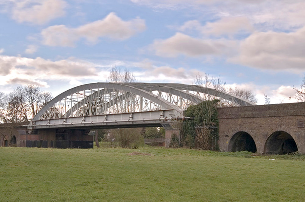
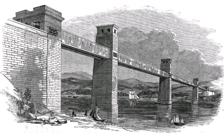
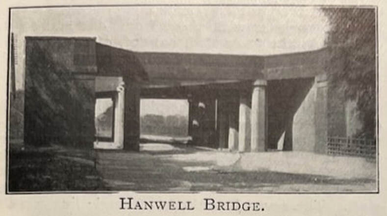
Of exactly what was done and when following the devastating fire that cracked eight of the cast iron beams supporting the Hanwell Bridge, the public record is frustratingly incomplete. The 1870 biography of Isambard by his son says: ‘... he repaired the Hanwell Bridge with wrought iron’, and the contract for the 1906 replacement of the bridge credits the contractor with £100 for 100 tons of wrought and cast iron (the cast iron was from three of the columns that had been removed). It is an article in the Great Western Railway Magazine on the occasion of the final replacement of the rebuilt bridge that tells us most of what we know: When the railway was opened in 1838 the lines were carried by a cast iron bridge with timber decking; this was destroyed by fire in 1847, and from that year dates the bridge now to be removed. It was designed by Brunel, and consists of wrought iron box girders supported on brick abutments and cast iron columns. In the ten years since Brunel had designed the original Hanwell bridge, knowledge of the use of wrought iron in the construction of girder bridges had grown exponentially, as had the availability of that material. Brunel himself was finalizing the design of a railway bridge at Windsor in wrought iron. It was a 200 foot span bowstring arch of the type that he would probably have used at Hanwell had the technology been available then. Robert Stephenson had already started construction of a stupendous wrought iron tubular girder bridge using several 400 foot spans to cross the Menai Straits. Stephenson had tasked William Fairbairn with testing different riveted wrought-iron structures with a view to finding the optimum design for a girder made of that material. Wrought iron was more expensive than cast iron since it had to be worked in molten form to remove excess carbon and other impurities, and then hammered or forged into bars or plates. To manufacture girders, parts had to be cut, bent, drilled, and riveted together. The problem of invisible air bubbles or other casting faults was effectively eliminated; wrought iron could be forged into thin plates and readily bent, and its resistance to tensile forces was three times greater than cast iron. Furthermore, unlike cast iron which tended to break without warning under excessive loads, wrought iron structures would bend beyond the elastic limit or crumple relatively slowly. It was therefore intrinsically a much more versatile and safer material to use for bridges. The conventional form of a girder was an I-beam, with a top and bottom flange connected by a vertical part called the web. The cast iron girders used by Brunel in the Hanwell Bridge had been of this form. The depth of the main girders—the ones that initially failed—was two foot two inches, the flanges were eleven inches wide, the thickness of the flanges and web was four and a half inches, and the length was thirty-four feet. As noted earlier, the weight of each was just under eight-and-a-half tons, and they had been ‘proved’—supported at their ends and loaded with test weights—to seventy-eight tons. An I-beam under load experiences compression, or a ‘crushing’ force, in the top flange, while the bottom flange comes under tension. Cast iron is immensely strong under compression, but five or six times weaker in tension, and it was this weakness under tension that necessitated the beams to be so massive in order to provide sufficient cross-sectional area in the bottom flange to withstand the design load. Fairbairn’s findings with wrought iron were that a rectangular ‘tube’ or box was the best configuration, improved considerably by a cellular top which provided the optimum resistance against crushing forces, and this was the design adopted by Stephenson for his Menai Straits bridge. And notwithstanding the greater intrinsic cost of wrought iron and the extra work needed, Fairbairn showed that a riveted wrought iron I-beam was virtually the same overall cost—while using just 40% of the iron—as a cast iron beam capable of bearing the same load. The Hanwell Bridge could have been entirely and securely reconstructed using a wrought iron bowstring girder like the Windsor design. But cost was clearly a factor as Brunel himself was later to remark—see below—and much of the existing structure was undamaged and could be reused. There was also the question of the effect of a lengthy disruption to railway services. It was decided to rebuild the bridge using wrought iron box girders supported on the existing pillars and abutments. The photograph accompanying the 1906 article on the bridge reconstruction taken shortly before it was demolished shows that, by comparison with the J C Bourne lithograph of the original bridge, the appearance was largely unchanged. All that is known about the actual construction seems to be contained in an incomplete set of just three rather poor drawings that have survived in Network Rail archives. There is a plan of the entire bridge which confirms that the general layout was the same as before, with longitudinal girders over the tops of the pillars, and transverse girders across the road. The number of load-bearing transverse girders had been reduced from thirteen to eight, and there are at least three different box girder designs, each one a depth of around two foot three inches, about the same depth as the cast iron girders they replaced. Widths varied between two and three feet, with numbers of cells—depth six inches—between four and zero. Tantalisingly, the nature of the bridge deck is quite unclear. There would have to have been substantial support for the rail timbers over the gaps between girders some of which were twelve feet apart. The plan appears to show a ‘cattle grid’ of further box girders between each transverse beam. Reference to another drawing identifies these as ‘Imitation girders’ consisting of a shallow box section top, two feet wide by around six inches deep—with a very thin-wall box-obviously not designed for load-bearing—below. A much later note on the plan states: ‘Weight of floor 26 lbs per square foot’ which is consistent with the entire deck being composed of shallow box section.
The plan also shows that all of the girders—longitudinal, transverse, and diagonal—were riveted together making an immensely strong integrated unit. They were designed with economy and elegance showing that Fairbairn’s experimental results had been fully absorbed and acted on. (Had Stephenson made Fairbairn's results available to his friend?) Construction must have presented some interesting problems, since most joints were riveted, and the top cells were only eight inches wide by six deep. To close a rivet it is necessary to access both sides—one for hammering, the other for the tool which holds the rivet in the hole as it is hammered from the other side, although hydraulic riveting machines were just starting to be used at the time. The plans do show that some joints, ‘Lap joint for last side plates’, were closed with nuts and bolts. Whatever the actual constructional details were, the process of rebuilding the bridge must have been a logistical nightmare. The new girders were the same depth as the ones they replaced but the fixings were entirely different and definitely not compatible. The bridge was also badly damaged from the fire and supported by timber framing. Could the work have been done piecemeal without closing the entire bridge? Closure even for a short period would have inflicted severe damage on the reputation and revenue of the company. The new girders did have one very considerable extra advantage over the cast iron girders they replaced: since they were riveted together from a number of small parts, they could be built up bit by bit in situ. Removing the old girders would be problematic, but it is possible to envisage a procedure whereby the bridge deck was wedged up an inch or so on timber supports. The cast iron girders could then be removed piecemeal and the box girders installed. Raising the bridge deck even by an inch would destroy Brunel’s ‘billiard table’ and a severe speed limit would have to be enforced, but this would be far better than closing the bridge completely. Furthermore something of the sort must have been done following the 1839 girder failure in order to replace the broken beam with its multiple fixings to the transverse girders. Much of the foregoing is speculation in the absence of any evidence to the contrary. The complete closure of the bridge for several months or even weeks and the corresponding disruption to road and rail traffic would surely have been noted in the newspapers, both local and national, and no such stories exist. Along with the uncertainty in the exact design used and method of construction, there is very little to confirm exactly when the bridge was rebuilt. There is a clue in a letter Brunel wrote to one of the GWR directors on the question of cast iron girders. On April 18 1849, he wrote: ... our Great Western road bridge at Hanwell, which, since 1838, has always been under repair, [and] has cost its first cost three times over ... I never use cast iron if I can help it; but in some cases it is necessary ... The tendered cost from Grissell and Peto for building the original Hanwell bridge had been £6750. There were the costs of replacing the two failed girders—the responsibility of the contractors—but the majority of the extra £13,500 must have been accrued by the wrought iron rebuild. It is likely, therefore, that it was either complete or well underway by the date of Brunel’s letter.
0 Comments
Leave a Reply. |
AuthorWelcome to the Mirli Books blog written by Peter Maggs Archives
March 2024
Categories |


 RSS Feed